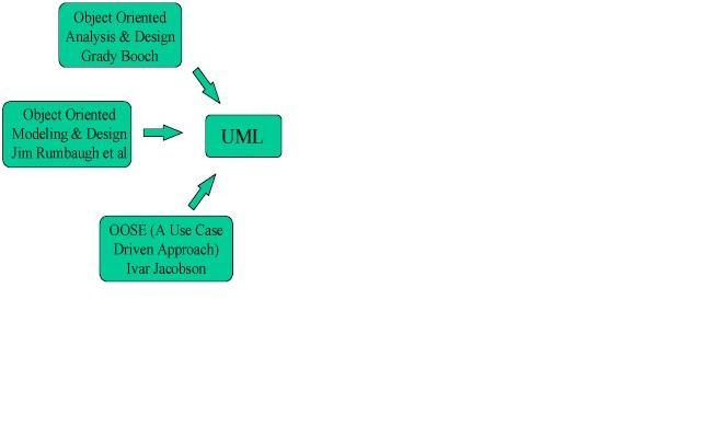
UML is definitive software modeling language. This emerged in the mid 1990’s with the standard driven from the Object Management Group TM or OMGTM. It is a graphical language with a set of semantics and rules. UML was developed to reduce the communication inefficiencies between various stakeholders within a project .The rules are explained in a form known as Object Constraint Language (OCL) which uses simple logic for specifying the properties of a system. UML has integrated the notations from the union of Booch method, the Object-modeling technique (OMT) and Object-oriented software engineering (OOSE) into a single, common and widely usable modeling language.
The goals in the design of UML were
•To provide an expressive, ready- to-use visual modeling language that can develop and exchange meaningful models.
•To provide a formal basis for understanding the modeling language and support higher-level development concepts.
•Integrate best practices and methodologies.
UML defines nine graphical diagrams such as Class diagram, Use-Case diagram, Behaviour diagram (Interaction, Sequence, and Collaboration diagram), Statechart diagram, Activity diagram, Implementation diagram (Component, Deployment diagram) where not all are used in practice.
•Class diagram -It is developed through Use-case, Sequence and Collaboration diagrams. It represents the class structure of the system with relationships between classes and inheritance structure.
•Use-Case diagram-It is a scenario-building approach in which we model the processes of the system.
•Behaviour diagram-It comprises three divisions such as Interaction, Sequence, and Collaboration diagram. Sequence diagram are mainly used in dynamic modelling situations. Collaboration diagram is all about showing in a scenario how objects interrelate in a system and Interaction diagram is used to examine the behaviour of objects within a single use case.
•Statechart diagram – It’s also used in dynamic modeling situations that specifically describe the events occurring within a single object in a system.
•Activity diagram- It is used to model the entire business process.
•Implementation diagram shows the implementation phase of systems development, such as the source code and runtime implementation structures. It comprises the component diagram which is usually represented as a graph that models the physical components such as the user interface part of the system and Deployment diagrams are used in conjunction with the component one in representing the physical modules in a system.
The choice of what models and diagrams one chooses and creates entirely depends on the problem scenario and how the corresponding solution is shaped to it. UML combines best techniques from data modeling, business modeling ,object modeling, and component modeling concepts. It can be used with all processes, throughout the software development life cycle, and across different implementation technologies. On the other hand, the main disadvantage was that it does not support other diagrams to be used in it like the data flow diagram (DFD) as they do not fit into the object oriented paradigm. Also, the comments from various blogs and reports read out to be ‘’Advanced concepts of UML are well documented in theory but little formulated in practice’’. Finally, the interesting fact on UML graphical notations is that it can define a model itself in addition to system’s components; this is called as a meta- model. It does provide a single, common and definitive statement of the syntax and semantics of the elements in the UML.
Resources:
A brief guide to the Standard Object Modeling Language (2nd Edition) by Martin Fowler and Kendall Scott (Addison Wesley, 1999)